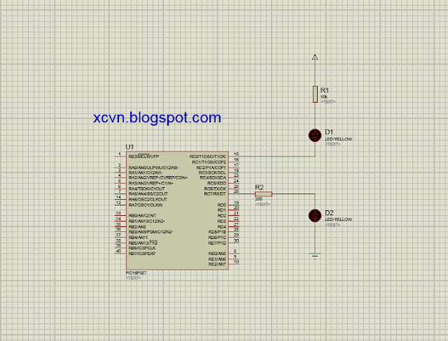
- Đây là ảnh mô phỏng protues.
- Đây là code chương trình.
#include <xc.h>
#define _XTAL_FREQ 4000000
// #pragma config statements should precede project file includes.
// Use project enums instead of #define for ON and OFF.
// CONFIG1
#pragma config FOSC = XT // Oscillator Selection bits (XT oscillator: Crystal/resonator on RA6/OSC2/CLKOUT and RA7/OSC1/CLKIN)
#pragma config WDTE = OFF // Watchdog Timer Enable bit (WDT disabled and can be enabled by SWDTEN bit of the WDTCON register)
#pragma config PWRTE = OFF // Power-up Timer Enable bit (PWRT disabled)
#pragma config MCLRE = OFF // RE3/MCLR pin function select bit (RE3/MCLR pin function is digital input, MCLR internally tied to VDD)
#pragma config CP = OFF // Code Protection bit (Program memory code protection is disabled)
#pragma config CPD = OFF // Data Code Protection bit (Data memory code protection is disabled)
#pragma config BOREN = OFF // Brown Out Reset Selection bits (BOR disabled)
#pragma config IESO = OFF // Internal External Switchover bit (Internal/External Switchover mode is disabled)
#pragma config FCMEN = OFF // Fail-Safe Clock Monitor Enabled bit (Fail-Safe Clock Monitor is disabled)
#pragma config LVP = OFF // Low Voltage Programming Enable bit (RB3 pin has digital I/O, HV on MCLR must be used for programming)
// CONFIG2
#pragma config BOR4V = BOR40V // Brown-out Reset Selection bit (Brown-out Reset set to 4.0V)
#pragma config WRT = OFF // Flash Program Memory Self Write Enable bits (Write protection off)
void GPIO_init (void);
void Anode (void);
void Cathode (void);
void main (void)
{
GPIO_init();
while(1)
{
__delay_ms(100);
Anode();
Cathode();
__delay_ms(100);
}
}
void GPIO_init(void)
{
TRISCbits.TRISC0 = 0; // RB0 LÀ OUTPUT
TRISCbits.TRISC7 = 0; // RB7 LÀ OUTPUT
PORTCbits.RC0 = 1; // OFF LED RB0
PORTCbits.RC7 = 0; // OFF LED RB7
}
void Anode (void)
{
PORTCbits.RC0 = 0;
__delay_ms(500);
PORTCbits.RC0 = 1;
}
void Cathode (void)
{
PORTCbits.RC7 = 1;
__delay_ms(500);
PORTCbits.RC7 = 0;
}
- Link download project : Click here#define _XTAL_FREQ 4000000
// #pragma config statements should precede project file includes.
// Use project enums instead of #define for ON and OFF.
// CONFIG1
#pragma config FOSC = XT // Oscillator Selection bits (XT oscillator: Crystal/resonator on RA6/OSC2/CLKOUT and RA7/OSC1/CLKIN)
#pragma config WDTE = OFF // Watchdog Timer Enable bit (WDT disabled and can be enabled by SWDTEN bit of the WDTCON register)
#pragma config PWRTE = OFF // Power-up Timer Enable bit (PWRT disabled)
#pragma config MCLRE = OFF // RE3/MCLR pin function select bit (RE3/MCLR pin function is digital input, MCLR internally tied to VDD)
#pragma config CP = OFF // Code Protection bit (Program memory code protection is disabled)
#pragma config CPD = OFF // Data Code Protection bit (Data memory code protection is disabled)
#pragma config BOREN = OFF // Brown Out Reset Selection bits (BOR disabled)
#pragma config IESO = OFF // Internal External Switchover bit (Internal/External Switchover mode is disabled)
#pragma config FCMEN = OFF // Fail-Safe Clock Monitor Enabled bit (Fail-Safe Clock Monitor is disabled)
#pragma config LVP = OFF // Low Voltage Programming Enable bit (RB3 pin has digital I/O, HV on MCLR must be used for programming)
// CONFIG2
#pragma config BOR4V = BOR40V // Brown-out Reset Selection bit (Brown-out Reset set to 4.0V)
#pragma config WRT = OFF // Flash Program Memory Self Write Enable bits (Write protection off)
void GPIO_init (void);
void Anode (void);
void Cathode (void);
void main (void)
{
GPIO_init();
while(1)
{
__delay_ms(100);
Anode();
Cathode();
__delay_ms(100);
}
}
void GPIO_init(void)
{
TRISCbits.TRISC0 = 0; // RB0 LÀ OUTPUT
TRISCbits.TRISC7 = 0; // RB7 LÀ OUTPUT
PORTCbits.RC0 = 1; // OFF LED RB0
PORTCbits.RC7 = 0; // OFF LED RB7
}
void Anode (void)
{
PORTCbits.RC0 = 0;
__delay_ms(500);
PORTCbits.RC0 = 1;
}
void Cathode (void)
{
PORTCbits.RC7 = 1;
__delay_ms(500);
PORTCbits.RC7 = 0;
}


2 nhận xét
Write nhận xétdạ anh ơi ...có thể giải đáp em tí hông ạ
Replybạn cần hỗ trợ gì ?
ReplyEmoticonEmoticon